BOW AIM SIGNAL CONVERTER
Patent Number: US 11566870 Grant Date: 2023-01-31 Filing Date: 2022-07-19
Overview
Filed on July 19, 2022 and granted on January 31, 2023, this U.S. patent captures a tightly integrated electromechanical and optical solution that brings automated ranging and ballistic compensation directly to traditional bow sights. Inventors based in Amarillo, TX and Niwot, CO developed a system that combines laser rangefinder hardware, embedded processors and a device application with an optical coupling assembly to route LED light into fiber-optic sight pin leads. The result is a compact module that interprets range and sensor data, computes a range-display signal with pin-specific tolerance logic, and drives selected sight pins as visible aiming cues without modifying the sight’s external pins. The specification addresses robust mechanical integration (watertight housing, neoprene LED surround and lead-receiver squeeze assemblies) and optical isolation to prevent cross-talk between channels while placing LEDs directly on a primary PCB for reliable alignment and serviceability.
Key Features
- Embedded device application with a pin-lighting algorithm that maps measured range to calibrated pin ranges and display actions (colors, blinking, intensity).
- Optical coupling assembly (LED surround, lead tunnels, optical line holders) that channels LED output into fiber-optic sight leads and prevents light pollution between pins.
- Integrated sensors (multi-axis gyroscope, pressure/temperature inputs) supporting ballistic adjustments and orientation-aware display.
This patent showcases precise, field-ready integration of optics, electronics and software for competitive and hunting archery. Its approach illustrates broader trends in sensor-driven aiming devices and embedded optical interfaces across sports and defense accessories.
Invention Details
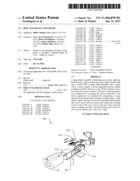
Abstract: A range finder assembly comprising one or more sight pin leads having a light emitting end and a light receiver end, one or more PCBs, a range finder assembly, one or more LEDs, a power supply, a device application and an optical coupling assembly. The one or more PCBs comprises one or more processors and a memory. The one or more processors are configured for executing the device application. The device application is configured for interpreting a range signal from the range finder assembly and generating a range display signal. The one or more LEDs generate light signals. The one or more LEDs are selectively routed into the light receiver end of the one or more sight pin leads using the optical coupling assembly. The light emitting end connect to one or more display pins within bow sight.
Summary of the Invention: A range finder assembly for coupling one or more display pins with one or more LEDs, measuring a distance to a target and displaying a range display signal on said one or more display pins is disclosed. Comprising said range finder assembly comprising one or more sight pin leads having a light emitting end and a light receiver end, one or more PCBs, a range finder assembly, said one or more LEDs, a power supply, a device application and an optical coupling assembly. Said one or more PCBs comprises one or more processors and a memory. Said one or more processors are configured for executing said device application. Said device application is configured for interpreting a range signal from said range finder assembly and generating said range display signal. Said one or more LEDs generate light signals. Said one or more LEDs are selectively routed into said light receiver end of said one or more sight pin leads using said optical coupling assembly. Said light emitting end connect to said one or more display pins within bow sight. each among said one or more display pins correspond to a bow sight aiming point of said bow sight. Said device application is configured to associate each among said one or more display pins and said one or more LEDs with a pin number and a pin range. Said range finder assembly is configured to communicate a summary of said range signal to said bow sight by sending said range display signal to said one or more LEDs, displaying said range display signal using said light signals on said one or more LEDs, routing said light signals into said light receiver end of said one or more sight pin leads using said optical coupling assembly, and displaying said range display signal on said one or more display pins. An LED surround is configured to slide around a portion of said one or more LEDs and hold a portion of said one or more LEDs at one end and a portion of a plurality of lead tunnels at another end.
Patent Document
Related: Computer Science & Software | Mechanical Engineering | Electrical Engineering | Security | Software And Electronics | Sports And Recreation | Testing And Measurement | Amarillo, Texas | Shannon Warren, Patent Attorney