Cascading Liquid Air Removal Filter System and Method
Patent Number: US 8757258 Grant Date: 2014-06-24 Filing Date: 2011-08-06
Overview
Filed August 06, 2011 and granted June 24, 2014, this patent protects a downhole filter concept that reduces air entrainment and protects pumps by converting high-energy cascading flow into a low-energy trickle before it reaches the pump intake. Developed by inventors based in Texhoma, OK, the disclosure describes a bristle-based element installed in the annular space between a well column and casing, positioned above the drawdown level so that falling liquid is forced through only non-linear, tortuous passages formed by densely packed bristles. The design’s outside diameter is sized to engage the casing interior, allowing the bristles to scrape debris during installation and to substantially fill the annulus to ensure flow is directed through multiple non-linear paths. The specification also covers practical installation approaches — sliding the assembly over a column section, replacing a column section, or welding for secure attachment — and contemplates common pump types including centrifugal and submersible units. The claims and specification were drafted to capture the structure, installation methods, and functional flow behavior to deliver robust IP protection for a pragmatic filtration solution.
Key Features
- Bristle element creating only non-linear fluid passages
- Installed between column and casing above drawdown level
- Outside diameter sized to engage casing internal diameter
- Compatible with centrifugal and submersible pumps
- Simple installation: slide-on, section replacement, or weld
This invention reduces air bubble ingestion and associated pump wear, offering immediate operational benefits for water and hydrocarbon well systems while addressing broader reliability concerns in downhole fluid handling.
Invention Details
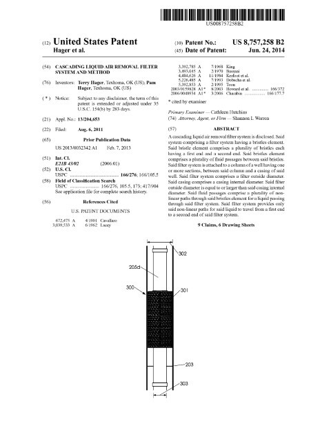
Abstract: A cascading liquid air removal filter system is disclosed. Said system comprising a filter system having a bristles element. Said bristle element comprises a plurality of bristles each having a first end and a second end. Said bristles element comprises a plurality of fluid passages between said bristles. Said filter system is attached to a column of a well having one or more sections, between said column and a casing of said well. Said filter system comprises a filter outside diameter. Said casing comprises a casing internal diameter. Said filter outside diameter is equal to or larger than said casing internal diameter. Said fluid passages comprise a plurality of non-linear paths through said bristles element for a liquid passing through said filter system. Said filter system provides only said non-linear paths for said liquid to travel from a first end to a second end of said filter system.
Background: (1) BACKGROUND (2) This disclosure relates generally to a cascading liquid air removal filter system and method. In one embodiment, this disclosure relates to said cascading liquid air removal filter system and method installed in a well containing a water pump installed therein. In another embodiment, said cascading liquid air removal filter system and method can be installed in a well producing liquids other than water, such as an oil from an oil well. (3) In one embodiment, said water pump installed in said well can comprise a centrifugal pump. In one embodiment, said centrifugal pump can be a rotodynamic pump that uses a rotating impeller to increase the pressure of a fluid. Said fluid enters said rotating impeller along or near a rotating axis of said rotating impeller and accelerated by said impeller, flowing radially outward into a diffuser or volute chamber (casing), from where it exits into a downstream piping system. In one embodiment, said water pump can comprise a turbine pump (i.e., a pump driven by a shaft driven form above surface), or a submergible pump. In one embodiment, said submergible pump can comprise an electrical pump located below a liquid surface and proximate to a bottom end of a well casing wherein a pipe contains and electrical line to said water pump. (4) When used in a water pump, water pumps (such as a centrifugal pump) encounter many problems. First, pumps with an impeller can become worn with continuous use, especially where said impeller encounters friction due to suspended solids in a liquid being pumped. Next, pumps can overheat due to low flow in liquid. Where pumps become worn, they can thereby have leakage occur along the rotating shaft. Further, many pumps, such as centrifugal pumps, must be filled with a fluid to be pumped in order to operate; that is, many pumps will not operate unless primed. In many cases, where a pump casing becomes filled with vapors or gases, said pump’s impeller becomes gas-bound and incapable of pumping. (5) In one embodiment, to ensure that a centrifugal pump remains primed and does not become gas-bound, said centrifugal pumps are placed below a fluid source level, from which the pump is to take its suction. The same effect can be gained by supplying liquid to said pump’s intake under pressure supplied by another pump placed in a suction line. Such an embodiment fails to account for air in said fluid source pushed below said fluid source level by cascading water. For example, in one embodiment, a water pump can be placed under water below a water level; wherein, said water pump typically draws said water into said pump but occasionally draws in air pushed below said water level by cascading water splashing at said water level. (6) In one embodiment, a pump can comprise one or more bowls which spin to push liquid through said pump. Where air is introduced into a fluid intake of said pump, non-uniformity at said fluid intake causes said bowls
Patent Document
Related: Mechanical Engineering | Oil & Gas | Fluid Systems | Shannon Warren, Patent Attorney