Fence Picket Alignment Tool and Method of Use
Patent Number: US 12129681 Grant Date: 2024-10-29 Filing Date: 2022-01-21
Overview
Filed in January 2022 and granted in October 2024, this patented alignment tool addresses a common shortcoming in fence construction by providing a robust, slide‑on guide that replaces the fragile string‑and‑eye method. Inventors based in Amarillo, TX developed a body-mounted picket level indicator that clamps to a cross member via adjustable upper guides and a spring‑loaded lower guide assembly. The device selectively attaches to and slides along the cross member, using wheels or low‑friction sliders to move forward and back while holding a precisely positioned level edge for consistent picket tops. The picket level indicator can be adjusted across a range of heights, pivoted to match an existing picket, and set for a level length long enough to cover multiple pickets before repositioning, improving installation speed and repeatability on uneven ground or angled installations. The firm’s drafting captured detailed mechanical features—spring assemblies, wheel axles, elongated apertures for fine adjustment, and interchangeable slider or wheel options—demonstrating careful claim construction to protect both structure and function.
Key Features
- Slideable clamp design with adjustable guide gap and spring‑loaded lower guide
- Wheel or polyurethane slider options for low friction movement
- Height‑adjustable, pivoting picket level indicator with quick‑release fastening
- Configured to follow ground angle for consistent aesthetic alignment
This practical mechanical innovation streamlines fence assembly for contractors and improves quality control in residential and commercial fence installation, reflecting clear commercial and technical relevance.
Invention Details
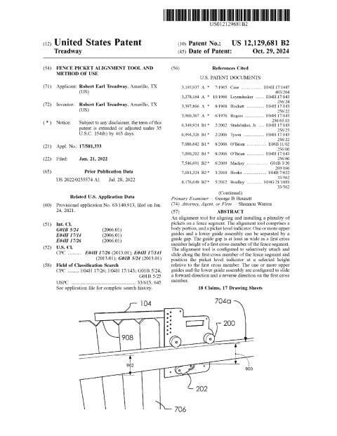
Abstract: An alignment tool for aligning and installing a plurality of pickets on a fence segment. The alignment tool comprises a body portion, and a picket level indicator. One or more upper guides and a lower guide assembly can be separated by a guide gap. The guide gap is at least as wide as a first cross member height of a first cross member of the fence segment. The alignment tool is configured to selectively attach and slide along the first cross member of the fence segment and position the picket level indicator at a selected height relative to the first cross member. The one or more upper guides and the lower guide assembly are configured to slide a forward direction and a reverse direction on the first cross member.
Summary of the Invention: An alignment tool for aligning and installing a plurality of pickets on a fence segment. Said alignment tool comprises a body portion, and a picket level indicator. One or more upper guides and a lower guide assembly can be separated by a guide gap. Said guide gap is at least as wide as a first cross member height of a first cross member of said fence segment. Said alignment tool is configured to selectively attach and slide along said first cross member of said fence segment and position said picket level indicator at a selected height relative to said first cross member. Said one or more upper guides and said lower guide assembly are configured to slide a forward direction and a reverse direction on said first cross member. Said alignment tool is selectively attached to said first cross member by: adjusting said guide gap between said one or more upper guides and said lower guide assembly to be substantially equal to said first cross member height of said first cross member, and squeezing said first cross member with said one or more upper guides on a cross member top edge and said lower guide assembly on a cross member bottom edge. a portion of said one or more upper guides and said lower guide assembly comprises a wheel configured to roll across a surface. Said one or more upper guides comprises a first upper wheel, and a second upper wheel. said alignment tool (100) is configured for aligning and installing said plurality of pickets on said fence segment by: selectively attaching to said first cross member of said fence segment, extending upward with said body portion from said one or more upper guides, extending outward from said body portion without said picket level indicator and defining a top edge of said plurality of pickets using a leveler lower edge of said picket level indicator at said selected height. Said lower guide assembly comprises a spring pressure configured to press a wheel portion of said lower guide assembly upward when released.
Patent Document
Related: Mechanical Engineering | Construction | Amarillo, Texas | Shannon Warren, Patent Attorney