Irrigation Wheel Traction Lug
Patent Number: US 9636944 Grant Date: 2017-05-02 Filing Date: 2014-12-03
Overview
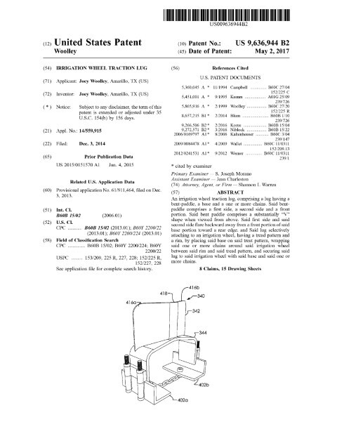
This patented wheel-traction innovation addresses a common operational challenge for center-pivot irrigation systems: wheels bogging in muddy or soft soils. Filed on December 3, 2014 and granted on May 2, 2017, the disclosure—by inventors based in Amarillo, TX and with the applicant based in Amarillo, TX—describes a lug that combines a V‑shaped bent paddle, a shaped base, adjustable lower brackets and a chain assembly to secure the device to a variety of irrigation wheels. The bent‑paddle geometry flares rearward from a front portion to increase bite into soil while avoiding the mud‑trapping cavities found in prior straight‑paddle designs. Modular lower portions and bolting assemblies clamp beneath the rim and allow the base to seat snugly between tread bars on plastic or rubber tires, and the chain assembly holds the lower brackets in tension for reliable retention under load.
Our prosecution emphasized robust claim language capturing the structural interactions (base, lower portions, chain assembly, and adjustable bolting) and the practical adaptability for multiple wheel types. The result is protection that reads on both retrofit and OEM attachment scenarios, reflecting careful drafting and technical depth.
Key Features
- V‑shaped bent paddle for improved soil engagement
- Base and adjustable lower portions that clamp to rims and fit between tread bars
- Chain assembly and bolting hardware for secure, adaptable attachment
- Compatible with plastic and rubber irrigation wheels
This traction lug enhances mobility and uptime for irrigation equipment and offers a practical component-level improvement with direct relevance to agricultural mechanization and field reliability.
Invention Details
Abstract: An irrigation wheel traction lug, comprising a lug having a bent-paddle, a base and a one or more chains. Said bent-paddle comprises a first side, a second side and a front portion. Said bent paddle comprises a substantially “V” shape when viewed from above. Said first side and said second side flare backward away from a front portion of said base portion toward a rear edge. and Said lug selectively attaching to an irrigation wheel, having a tread pattern and a rim, by placing said base on said treat pattern, wrapping said one or more chains around said irrigation wheel between said rim and said tread pattern, and securing said lug to said irrigation wheel with said base and said one or more chains.
Summary of the Invention: An irrigation wheel traction lug, comprising a lug having a bent-paddle, a base and a one or more chains. Said bent-paddle comprises a first side, a second side and a front portion. Said bent paddle comprises a substantially “V” shape when viewed from above. Said first side and said second side flare backward away from a front portion of said base portion toward a rear edge. and Said lug selectively attaching to an irrigation wheel, having a tread pattern and a rim, by placing said base on said treat pattern, wrapping said one or more chains around said irrigation wheel between said rim and said tread pattern, and securing said lug to said irrigation wheel with said base and said one or more chains.
Patent Document
Related: Agriculture | Mechanical Engineering | Transportation | Amarillo, Texas | Shannon Warren, Patent Attorney