Toilet Vent System
Patent Number: US 9290920 Grant Date: 2016-03-22 Filing Date: 2014-06-21
Overview
This patent describes a compact toilet vent system that separates odorous gases from sanitary fluid supply within a standard toilet tank. Filed December 21, 2012 and granted March 22, 2016, the claims capture an integrated assembly that routes a first fluid connection from the tank’s upper airspace to an external gas outlet while simultaneously routing a sealed second fluid connection that supplies water to internal tank components. Inventors based in Amarillo, TX and an applicant/assignee based in Dalhart, TX developed a solution that installs through an existing tank fluid input and uses cooperating manifolds, a snorkel, an up‑rod channel, and a buoyant floating vent to manage flow and prevent cross‑contamination. The floating vent opens when the tank is at normal fill to allow vacuum‑assisted exhaust of tank gases and reliably closes during flush/refill cycles to block mixing or leakage. The drafting captures sealing detail around the up‑rod and manifold interfaces, an outbound passage for gases, and an inbound channel for sanitary fluid, providing robust protection against unwanted gas return to the bowl without placing active components inside the wetted portion of the tank.
Key Features
- Dual fluid paths: separate outbound gas exhaust and inbound water supply
- Floating vent that opens/closes with tank water level
- Manifold and up‑rod sealing to prevent mixing
- Installs via existing tank fluid input; compatible with external fan/vacuum
By addressing both fluid mechanics and practical installation constraints, the invention improves sanitary ventilation in bathrooms and offers a practical route for retrofit ventilation and odor control in plumbing systems.
Invention Details
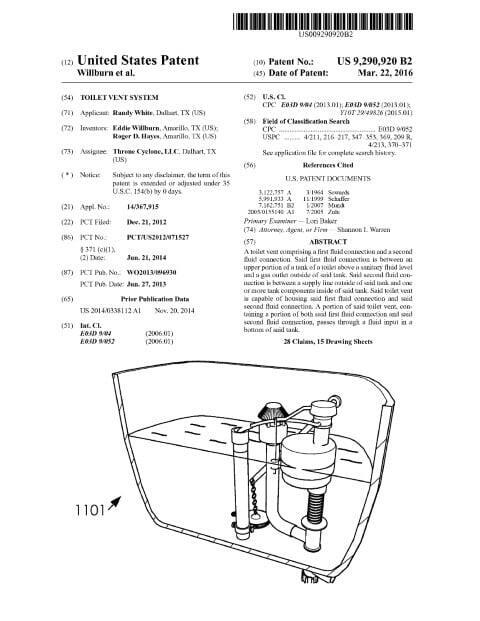
Abstract: A toilet vent comprising a first fluid connection and a second fluid connection. Said first fluid connection is between an upper portion of a tank of a toilet above a sanitary fluid level and a gas outlet outside of said tank. Said second fluid connection is between a supply line outside of said tank and one or more tank components inside of said tank. Said toilet vent is capable of housing said first fluid connection and said second fluid connection. A portion of said toilet vent, containing a portion of both said first fluid connection and said second fluid connection, passes through a fluid input in a bottom of said tank.
Summary of the Invention: A toilet vent system and method are disclosed. Said toilet vent system comprising a toilet vent. Said toilet vent comprising a first fluid connection and a second fluid connection. Said first fluid connection is between an upper portion of a tank of a toilet above a sanitary fluid level and a gas outlet outside of said tank. Said second fluid connection is between a supply line outside of said tank and one or more tank components inside of said tank. Said toilet vent is capable of housing said first fluid connection and said second fluid connection. A portion of said toilet vent, containing a portion of both said first fluid connection and said second fluid connection, passes through a fluid input in a bottom of said tank.
Said toilet vent method comprising installing a toilet vent having a first fluid connection and a second fluid connection into a tank of a toilet through a fluid input of said tank; connecting an upper portion of said tank to a gas outlet through said first fluid connection; connecting a supply line containing a sanitary fluid to one or more tank components in said tank. Said upper portion comprises an interior portion of tank above a fluid level of said sanitary fluid collected in said tank.
Patent Document
Related: Mechanical Engineering | Fluid Systems | Food Processing | Thermal Systems | Amarillo, Texas | Dalhart, Texas | Shannon Warren, Patent Attorney