TANK ASSEMBLY AND METHOD OF USE
Patent Number: US 10449657 Grant Date: 2019-10-22 Filing Date: 2017-09-22
Overview
This patent describes a robust tank assembly for controlled delivery of an abrasive slurry, incorporating dual blister assemblies, draw tubes, cone flanges, snorkels and dedicated spray equipment. Filed on September 22, 2017 and granted on October 22, 2019, the prosecution underscores careful claim drafting around coordinated fluid channels, rotating spray heads, and selectable slurry flow. Inventors based in Houston, TX developed the system and the applicant, MMLJ, Inc., is likewise based in Houston, TX. The firm’s patent work emphasizes mechanical detail and manufacturability—welding and pressure‑vessel considerations are claimed consistent with ASME code—while protecting the key interplay between cone flanges and draw tubes that enables selective channeling of slurry into independently rotating spray assemblies.
The disclosure addresses practical operational needs: separation distances between draw tubes prevent interference as spray equipment rotates, independent control boxes and air inlet hoses support simultaneous multi‑user operation, and snorkel and vibrator features ensure reliable material pickup and flow. These drafting choices secure claims on both structural elements and functional coordination that matter to operators of dust‑minimizing surface‑preparation systems.
Key Features
- Dual blister assemblies with separated draw tubes enabling independent rotating spray equipment
- Cone flanges and adjustable gaps to selectively channel slurry into draw tubes
- Integrated snorkel, air line and vibrator arrangements for reliable slurry movement
- ASME‑aware pressure vessel construction and multi‑operator capability
By protecting both the mechanical architecture and functional interplay of components, this patent strengthens commercial freedom for slurry‑based surface treatment systems and addresses industry demand for safer, dust‑controlled abrasive processes.
Invention Details
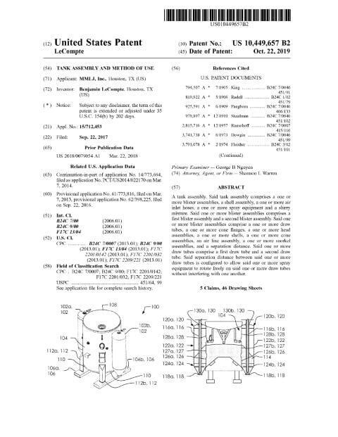
Abstract: A tank assembly. Said tank assembly comprises a one or more blister assemblies, a shell assembly, a one or more air inlet hoses, a one or more spray equipment and a slurry mixture. Said one or more blister assemblies comprises a first blister assembly and a second blister assembly. Said one or more blister assemblies comprise a one or more draw tubes, a one or more cone flanges, a one or more head assemblies, a one or more shells, a one or more cone assemblies, an air line assembly, a one or more snorkel assemblies, and a separation distance. Said one or more draw tubes comprise a first draw tube and a second draw tube. Said separation distance between said one or more draw tubes is configured to allow said one or more spray equipment to rotate freely on said one or more draw tubes without interfering with one another.
Summary of the Invention: A tank assembly. Said tank assembly comprises a one or more blister assemblies, a shell assembly, a one or more air inlet hoses, a one or more spray equipment and a slurry mixture. Said one or more blister assemblies comprises a first blister assembly and a second blister assembly. Said one or more blister assemblies comprise a one or more draw tubes, a one or more cone flanges, a one or more head assemblies, a one or more shells, a one or more cone assemblies, an air line assembly, a one or more snorkel assemblies, and a separation distance. Said one or more draw tubes comprise a first draw tube and a second draw tube. Said separation distance between said one or more draw tubes is configured to allow said one or more spray equipment to rotate freely on said one or more draw tubes without interfering with one another. Said one or more draw tubes selectively mate with said one or more cone flanges. Said one or more cone flanges are attached at a lower point in said one or more cone assemblies and gather portions of said slurry mixture. Said tank assembly is configured to selectively channel said slurry mixture into said one or more draw tubes by opening a gap between said one or more draw tubes and said one or more cone flanges.
A tank assembly. Said tank assembly comprises a one or more blister assemblies, a shell assembly, a one or more air inlet hoses, a one or more spray equipment and a slurry mixture. Said one or more blister assemblies comprises a first blister assembly and a second blister assembly. Said one or more blister assemblies comprise a one or more draw tubes, a one or more cone flanges, a one or more head assemblies, a one or more shells, a one or more cone assemblies, an air line assembly, a one or more snorkel assemblies, and a separation distance. Said one or more draw tubes comprise a first draw tube and a second draw tube.
Patent Document
Related: Mechanical Engineering | Oil & Gas | Fluid Systems | Materials | Houston, Texas | Shannon Warren, Patent Attorney